Hello All!

It has been a while since my last post. I had a lot to do all these days so my spare time was really cut down. In this post i'm going to write a small how to on how to fix possible rotary encoder problems on your OWON SDS7102 Oscilloscope. 

The issue:

Today while i was trying to read an analog signal using my OWON SDS7102 scope i realised that the Volts/div rotary encoder of Channel 1 didn't work as suspected. By turning the knob the value was jumping steps or do nothing ro changing direction. For example if channel 1 was set to 2V/div and the volts/div knob was turned one step right the value was jumping to 50V/div or to 20mv/Div or to another random value instead of 1V/div. 

In an older post i was analysing how a rotary encoder works. Brinking that post to my mind i thought that may be there is a filtering issue and the mcu reads most of the noise coming out of the encoder as a real output.

As a hardware engineer i always like to tear down the devices and see what is really going on inside. So i did and i reached the keyboard pcb.
OWON screws

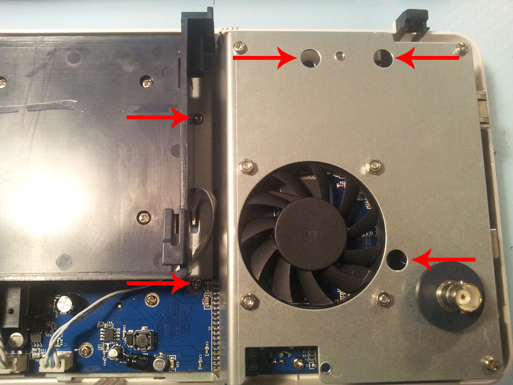
After removing the backside of the scope you only need to unscrew the 5 screws shown in the above photo in order to reach the keyboard. 

Owon keyboard pcb backside

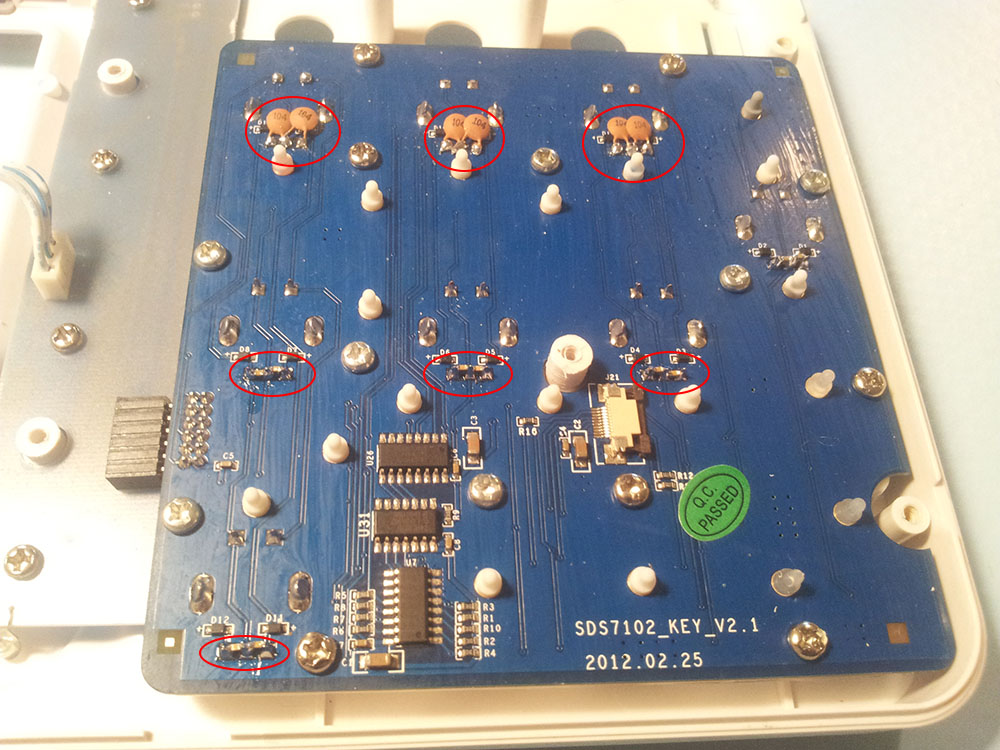
And… this is the keyboard back side. What i did was to solder two 100nF on each rotary encoder (one on each output) to filter the output signal. Each encoder has 3 pins in a row. The one in the middle is the GND and the other two on the sides are the outputs. As you can see in the above photo in the first raw i have soldered through hole capacitors and on the other two rows i have soldered SMD. Both types do the job and it's on your choice. 

After the reassembly of the oscilloscope i made a test and i show fully improved behaviour of all the knobs. The capacitors solved the problem and increased the quality of the knobs.

The conclusion is that the Chinese manufacturer may had chosen to make a software filter instead of adding these capacitors to reduce the cost but the software finally wasn't that good to filter all the noise. By adding these capacitors we reduced the noise going to the mcu from the rotary outputs and make software filter life easier. 

Now you can understand how important are the capacitors!


DHT-11 is a temperature & humidity sensor in one package. It utilizes exclusive digital-signal-collecting-technique and humidity sensing technology, assuring its reliability and stability. Its sensing elements is connected with 8-bit single-chip computer. Every sensor of this model is temperature compensated and calibrated in accurate calibration chamber and the calibration-coefficient is saved in type of program in OTP memory, when the sensor is detecting, it will cite coefficient from memory. Small size & low consumption & long transmission distance(20m) enable DHT-11 to be suited in all kinds of harsh application occasions.

Characteristics:

  • Low Cost
  • Supply voltage 3 to 5V
  • Max current 2.5mA (while requesting data)
  • 20-80% humidity range with 5% accuracy
  • 0-50C temperature range with +-2C

Inside the package looks like this:


SDC11305 Inside DHT-11

The interesting thing in this module is the protocol that uses to transfer data. All the sensor readings are sent using a single wire bus which reduces the cost and extends the distance.

In order to send data over a bus you have to describe the way the data will be transferred, so that transmitter and receiver can understand what says each other. This is what a protocol does. It describes the way the data are transmitted. 

On DHT-11 the 1-wire data bus is pulled up with a resistor to VCC. So if nothing is occurred the voltage on the bus is equal to VCC.

Request:

To make the DHT-11 to send you the sensor readings you have to send it a request. The request is, to pull down the bus for more than 18ms in order to give DHT time to understand it and then pull it up for 40uS.

Response:

What comes after the request is the DHT-11 response. This is an automatic reply from DHT which indicates that DHT received your request. The response is ~54uS low and 80uS high.

Data:

What will come after the response is the sensor data. The data will be packed in a packet of 5 segments of 8-bits each. Totally 5×8 =40bits.

First two segments are Humidity read, integral & decimal. Following two are Temperature read in Celsius, integral & decimal and the last segment is the Check Sum which is the sum of the 4 first segments. If Check Sum's value isn't the same as the sum of the first 4 segments that means that data received isn't correct.

How to Identify Bits:

Each bit sent is a follow of ~54uS Low in the bus and ~24uS to 70uS High depending on the value of the bit.

Bit '0' : ~54uS Low and ~24uS High

Bit '1' : ~54uS Low and ~70uS High

End Of Frame:

At the end of packet DHT sends a ~54uS Low level, pulls the bus to High and goes to sleep mode.


Logic Analyzer Snapshots

In the following image you can see the request sent from the MCU to the DHT and following the packet. Because the request has very long duration as you can see is about 20mS and packet received is in uS we can't view the data bits.

If we zoom at the data bits we can read the values. You can see after the Request follows the Response, and Data bits. I have drawn some color notes to be more understandable.

If we decode the above data we have.

Humidity 0b00101011.0b00000000 = 43.0%

Temperature 0b00010111 = 23 C.

The last two segments can't be seen in this image because of zoom.


Implementation:

What we have to do to read a DHT-11 sensor is:

  1. Send request
  2. Read response
  3. Read each data segment and save it to a buffer
  4. Sum the segments and check if the result is the same as CheckSum

If the CheckSum is correct, the values are correct so we can use them. If CheckSum is wrong we discard the packet.

To read the data bits can use a counter and start count uSeconds of High level. For counts > 24uS we replace with bit '1'.  For counts <=24 we replace with bit'0'


Here you can find some code to read DHT-11 using an Atmega8 at 16Mhz

DOWNLOAD HERE

The idea of explaining here how a rotary encoder works began from the need to use a rotary encoder myself for adjusting a pwm which drives a DC motor. So i started looking for how a rotary works. When i understood how it works i thought that it could be a good idea to show you and explain what i learned.

Anyone who has worked on circuits before has used an analog potentiometer. If you are new in electronics here is a quick explanation of what a potentiometer is. In a few words a potentiometer is a varying resistor which value changes by turning the knob. By the Ohm Law V=I*R implies that it can be used for voltage or current adjustments. An example of potentiometers use is in front panels for varying values e.g in a work bench power supply to adjust the voltage or the current.

Well the potentiometers have some disadvantage.

  • Produce noise at knob turn over the uses or if dust has passed in.
  • They are not that accurate.
  • To use them in a digital circuit you have to use an Analog To Digital converter.

On the other hand Rotary Encoder.

  • There is no noise production (if you use the appropriate capacitors).
  • They are accurate (they have steps).
  • There is no need of a digital to analog converter.

Also another difference is that the analog potentiometer has a stop and start point. Rotary encoder can be turned as many times as you want. There is no end and start point. Optically there is no big difference. The best way to find out if it is a rotary encoder is to turn the knob. If you feel steps and there is no start and end point it is a Rotary Encoder.

So Rotary Encoders can be used in digital circuits providing accuracy and ease of use. Analog potentiometers are easier to use in analog circuits.

A Rotary Encoder usually has 3 pins A, B and C. Pin C is the middle pin and we connect it to GND.

What a rotary encoder actually does is:

While you turn the knob it “short-circuits” pins A and B to pin C (GND) for some milliseconds depending on the speed you turn it. Actually this is the step you feel when you turn it. Which of the two pins is shorted first depends on the direction you turn the knob.

  • Right wise pin A will be first shorted to GND and then pin B.
  • Left wise pin B will be first shorted to GND and the pin A.

By this you can identify in which way the knob is turned to. To see the short circuit, you have to supply a voltage at pins A and B. If you don’t do it the voltage at pins A and B will be 0Volt before and after the short circuit so no difference will be observed. If you put direct voltage on these two pins when short circuit occurs a lot of current will be drawn as a result the power supply connected to, may be burned. For this reason we have resistors. They can adjust the current flow and they can hold voltage difference at their edges. By putting a pull up resistor on each pin(A & B) to supply voltage you pull them the supply voltage (that’s why the called pull ups) and when the short circuit is occurred their voltage drops to 0V as the GND. The current that will be drawn depends on the resistors value. With the Ohm Law V=I*R you can calculate it.

Above is a hand drawn schematic with the theoretical output pulses on the right. R1 and R2 are the pull up resistors i talked about before (In use with an MCU for better results don’t use MCU’s internal pull ups but external 10K’s). The real waveforms is expected to have noise provided by the turning of the knob as a push button provides as you push it. To clear this noise i have put two decoupling capacitors C1 and C2 (1uF each). Follow real images from a logic analyzer when the knob is turned with decoupling capacitor connected and not. Notice the difference!

Right Wise

Capacitor NO

Capacitor YES

Left Wise

Capacitor NO

Capacitor YES

We don’t care about the pulse width which depend on the speed you turn the knob. What we are interested in is which pin is getting first low. As you can see there is a big difference between waveforms with and without capacitors connected. Waveforms with capacitors connected are close to theoretical ones.

Actually the code exported from the 3-pin rotary encoder is a 2-bit gray code.

Left CCW

Right CW

A 0 0 1 1
B 1 0 0 1

A 1 0 0 1
B 0 0 1 1

We can identify in which direction is moving by just looking the B state after A’s falling edge. With red is colored the state after the falling edge of A.

Well now that we know how it works we can use it with a microcontroller by just checking which pin is getting first low. One way is to use an external interrupt with triggering on the falling edge of pin A as shown in the following diagram. If a falling edge detected on pin A check pin B state. If it is low that means that the rotary has turned left otherwise it has turned right.

The test Circuit

Rotary Encoder How To